
Page 22 - Summer 2007
P. 22
which is dramatically reduced by utilizing short-pulse, rather than continuous wave ultrasound. Finally, it suggests the marriage of acousto-optic and clinical diagnostic ultrasound imaging, where the clinical ultrasound machine is used to both generate conventional B-mode images and pump the acousto-optic signal. Since the same sound field is employed to affect both ultrasound scattering and acousto-optic sens- ing, the images are automatically co-registered, and multi- mode optical/acoustical imaging is realized. This approach, which has been successfully demonstrated using tissue mim- icking phantoms and excised tissue samples,18 is described in greater detail below.
Imaging by acousto-optic sensing
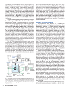
The experimental setup, shown in Fig. 4, combines the photorefractive crystal-based optical detection system with a commercially available, PC-based, diagnostic ultrasound scanner (AN2300, Analogic Corp.) employing a 5 MHz, 192 element linear phased array scanhead and a 64 channel beamformer. Light from a frequency-doubled Nd:YAG laser is sent to a variable beam splitter where it is split into signal and reference beams. The reference beam is directed around the test tank and sent to the photorefractive crystal-based interferometer. The signal beam is sent through a beam expander along the Y-axis to the sample. Light scattered from the sample is collected by a lens and directed into the pho- torefractive crystal, where it interferes with the reference beam. The photorefractive crystal-interferometer employs a bismuth silicon oxide (BSO) crystal (Bi12SiO20), and a high voltage AC electric field is applied to the crystal to enhance the two-wave mixing process. The signal beam and diffract- ed reference beam exiting the crystal are collected by an ava- lanche photodiode (APD), processed using a preamplifier and low-pass filter, and digitized in the oscilloscope.
Figure 5 shows acousto-optic signals observed in a high- ly scattering tissue phantom using a 3-cycle ultrasound pulse at a center frequency of 5 MHz. As the ultrasound propagates through the phantom, the magnitude of the acousto-optic signal (with respect to the steady-state background) gives a measure of the strength of the acousto-optic interaction and is affected by, among other things, the amount of light in the interaction region, the ultrasound pressure, and the sensing volume. In the case when the ultrasound passes through a homogeneous region of tissue phantom (Traces A and C), the signal tracks the envelope of the background light distribu- tion, with the spatial resolution controlled by the ultrasound beam width and pulse length. If there is an optical absorber embedded in the phantom, the magnitude of the acousto- optic signal decreases when the ultrasound pulse passes the absorber (Trace B). This is because, once the acoustic pulse enters the optical absorber, there is relatively little light avail- able to modulate. In a sense, the acousto-optic interaction region acts like a virtual light sensor that probes the local optical properties of the medium. By using commercial ultrasound imaging technology, this “sensor” can be made to travel along electronically beam-formed trajectories at the speed of sound.
Recall that a primary advantage of photorefractive crys- tal-based detection of acousto-optic signals is that the sensi-
signal beam, and the two beams interfere constructively at the detector. In the presence of ultrasound, the phase of the signal beam is shifted with respect to the reference, leading to a decrease in the intensity at the detector. This allows for coher- ent summation of signals detected over a large number of speckles, regardless of the fact that the phase shift imparted on the diffuse optical field by the ultrasound is spatially random. The resulting acousto-optic signal is not at the ultrasound fre- quency, but rather is manifested as a DC offset signal that tracks the instantaneous flux of modulated light incident on the detector.
A related photorefractive crystal based detection approach has also been presented in which the reference beam to the photorefractive crystal is frequency shifted by an amount equal to the ultrasound frequency and continuous wave ultra-
17
sound is employed. Only the ultrasound modulated (fre-
quency shifted) light from the sample forms a static interfer- ence grating in the crystal. The strength of this grating thus gives a measure of the amplitude of the acousto-optic interac- tion. In general, photorefractive crystal-based acousto-optic systems offer a higher étendue, or light collection ability, than previously developed techniques thus making them an attrac- tive option for deep tissue imaging applications. The photore- fractive crystal-based detector also accommodates physiologi- cal motion as it can respond quickly enough to rewrite the index of refraction grating and automatically adapt to motion- induced changes in the speckle pattern.
The fact that the photorefractive crystal-based system accommodates pulsed acousto-optic sensing at clinically rel- evant exposure levels is significant for three reasons. First and foremost, the spatial resolution of the measurement is determined by the spatial extent of the acoustic field. By uti- lizing high-frequency pulsed ultrasound, the lateral and axial resolutions are determined primarily by the width of the beam and the spatial pulse length. Secondly, thermal bioef- fects scale with the average intensity of ultrasound exposure,
Fig. 4. Experimental setup for acousto-optic imaging using a photorefractive crys- tal based interferometry system and a commercial ultrasound scanner to pump the acousto-optic response. Electronically scanned images are generated in the X-Z plane. By mechanically scanning along the Y axis, three-dimensional acousto-optic imaging is realized.
20 Acoustics Today, July 2007
