
Page 23 - Summer 2007
P. 23
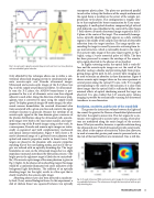
  transparent plastic plates. The plates are positioned parallel to each other to keep the thickness of the sample uniform and the signal beam is incident on the center of the sample, per- pendicular to the plates. This configuration is roughly simi- lar to that employed for breast examination by X-ray mam- mography. A small optical absorber, composed of gel infused with India ink, was embedded at the center of the slab. Figure 7 (left) shows a B-mode ultrasound image acquired in the X- Z plane at the center of the target. The acoustically homoge- neous, optically absorbing target appears as a dark, uniform region in the middle of the sample; note the lack of detectable reflection from the target interface. The image speckle sur- rounding the target is caused by acoustic scattering from tis- sue microstructure, which is noticeably absent in the target. The acousto-optic image of the same target is given in Fig. 7 (right), using a 3-cycle acoustical pulse at 5 MHz. The data has been processed to remove the envelope of the acousto- optic signal observed in the absence of an absorber.
In highly scattering media, the optical field is truly dif- fuse and the acousto-optic images are not the result of the absorber casting a shadow and preventing light from propa- gating along a given path. In fact, acousto-optic imaging can be used to localize an absorber in three dimensions. Figure 8 shows acousto-optic images taken on the same specimen at several points along the optical (Y) axis, with Y=0 roughly corresponding to the center of the inclusion. It is clear from these images that the optical field is sufficiently diffuse that minimal effects of optical shadowing around the target are observed. It is also evident that 3-D acousto-optic volume imaging is possible by mechanically scanning the ultrasound transducer in one dimension.
Resolution, sensitivity, and the role of the sound field
The greater the interaction volume between the light and the sound, the greater the fluence of modulated photons and the better the signal to noise ratio. This fact argues for a con- tinuous wave approach to acousto-optic sensing, where pho- tons are modulated along the entire length of the acoustic beam. What you sacrifice, however, is spatial resolution along the ultrasound axis. Pulsed ultrasound provides axial resolu- tion, albeit at the expense of sensitivity. Pulses also allow you to work at somewhat greater peak acoustic pressure levels, as the risk of thermal bioeffects are minimized. One is still lim-
 Fig. 5. Acousto-optic signals measured along several scan lines in a tissue phantom with an embedded optical absorber.
  Fig. 6. B-mode ultrasound (left) and acousto-optic images of a tissue phantom with two embedded inclusions. The inclusion on the right has been infused with an opti- cally absorbing dye.
 tivity afforded by this technique allows one to utilize a con- ventional ultrasound imaging system to simultaneously gen- erate acousto-optic and B-mode ultrasound images. Ultrasound and acousto-optic images of the X-Z plane (see Fig. 4) of the sample are produced as follows. To ultrasonical- ly scan the X-Z plane, the AN2300 beam-former is pro- grammed to fire a set of ultrasonic sector scan lines aligned adjacent to each other. Along the direction of ultrasonic prop- agation, time is converted to space using the sample sound speed. To display grayscale images (B-mode image), the ultra- sound scanner demodulates the received ultrasound echo train associated with a given scan line and converts the signal envelope function to grayscale. Because the envelope of an acousto-optic signal in the time-domain gives a measure of the photon distribution along the ultrasound path, acousto- optic images were built in the exact same manner, and super- imposed on top of the B-mode images using a color-scale. As a consequence, B-mode and acousto-optic images are intrin- sically co-registered and yield complementary mechanical and optical contrast information. Figure 6 (left) shows a B- mode ultrasound image of a gel-based tissue phantom with optical and acoustic properties similar to breast tissue. Two targets are placed in the phantom with acoustic properties matching that of the surrounding media, and one of the tar- gets was infused with an optically absorbing dye. The target boundaries are seen on the ultrasound image due to a slight impedance mismatch introduced by fabrication process. (The bright spot in the rightmost target is likely due to a microbub- ble.) The acousto-optic image of the same phantom is given in Fig. 6 (right). In the absence of an absorbing target, this image would be a uniformly illuminated red circle indicative of the background light distribution. The addition of an optically absorbing target (on the right) results in a blue spot that is clearly resolved in the acousto-optic image.
Absorbing objects have also been detected in moderate- ly thick (2 cm) excised biological tissue. In this experiment, a slab of chicken breast was squeezed between two optically
Illuminating Sound 21
