
Page 19 - Jan2013
P. 19
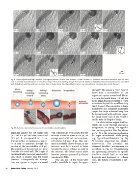
                  Fig. 9. Vascular rupture involving a liquid jet. Peak negative pressure = 4 MPa. Vessel diameter = 15 mm. In frame 4, a liquid jet is seen directed toward the right side vessel wall. In frame 12, the bubble appears as a mushroom shape with its stem stretching through the vessel wall. Sketches of the bubble in these characteristic frames are marked with the bubble in solid lines and vessel in dashed lines. In the last frame, the collapsed bubble (arrow) was observed in the interstitial space outside the vessel.
  Fig. 10. Illustration of potential mechanisms for microbubble-induced bioeffects.
expanded against the left vessel wall (0.3 and 0.6 μs) and then contracted (0.9 μs). It re-expanded at 1.2 μs. During further re-expansion, a micro- jet is seen to penetrate through the interior of the microbubble (1.8 μs). The direction of the microjet was away from the left vessel wall. The length of the (identifiable) microjet was about 38 μm, which is smaller than the vessel diameter. Consequently, the microjet does not appear to impact the vessel
site wall?” The answer is “yes!” Figure 9 shows how a microbubble jet can impact and rupture a vessel wall. The jet is seen in the fourth frame (1.6 μs), and the re-expanding microbubble is found in the tissue beyond the vessel boundary (last 3 frames). Our conclusion is that a microbubble in a compliant microvessel can jet, that the jet is directed away from the nearest vessel wall, and it can impact the distal vessel wall if the vessel is smaller than the length of the jet.
Our observations suggest that bio- effects can occur through distension, invagination, or jetting. We hypothe- size that invagination (like that shown in Fig. 5) is the principal mechanism for larger microvessels, while jetting (e.g., Figs. 8-9) and distension (e.g., Fig. 7) become important for smaller microvessels. The potential and observed bioeffect mechanisms are assembled in Fig. 10. Understanding and optimizing cavitation for specific bioeffects should lead to improved diagnosis and treatment at reduced costs. The future of healthcare is bub- bles! AT
 wall. Additionally, if we assume that the microjet started to form at 0.9 μs, an average speed of 42 m/s can be estimat- ed between 0.9 and 1.8 μs. This esti- mate is probably a lower bound, as the microjet may have started to form towards the end of collapse or early in the rebound. The lower bound water hammer pressure generated by this jet was about 63 MPa.
One can ask, “If the vessel were smaller, would the jet impact the oppo-
18 Acoustics Today, January 2013
