
Page 17 - Jan2013
P. 17
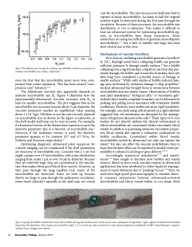
                  Fig. 4. The dilatational viscosity for Definity microbubbles is shown as a function of ambient microbubble size (radius). Reprinted.10
even the hint that the microbubble spent more time com- pressed than under expansion. This has been termed “com- pression only” behavior.13-14
The dilatational viscosity also apparently depends on ambient microbubble size R0. Figure 4 illustrates how the experimentally-determined viscosity increases with R0, at least for smaller microbubbles. The plot suggests that as the microbubble size increases beyond about 3 μm diameter, the viscosity parameter reaches an equilibrium value nearing about 1 x 10⁻⁸ kg/s. Whether or not the real viscosity depends on microbubble size as shown in the figure is unknown, as the shell model itself may not be very accurate. For example, if a linearized version of the Marmottant equation is used, the elasticity parameter also is a function of microbubble size.9 However, if the nonlinear version is used, the elasticity parameter appears to be constant (0.7 and 0.5 N/m, for Definity and Sonovue, respectively).10
Optimizing diagnostic ultrasound pulse sequences for contrast imaging can be complicated if the shell parameters are functions of microbubble size. Consider that a 1-ml vial might contain over 108 microbubbles, with a size distribution ranging from under 1 μm to over 10 μm in diameter. Because they are relatively large, they are constrained to the vascula- ture (this makes them good blood flow tracers). However, as they pass through the lung capillary bed, many of the microbubbles are destroyed. Some are held up because they’re too large to pass through the pulmonary circulation. Some break (dissolve) naturally as the shell may not evenly
coat the microbubble. The injection process itself may lead to rupture of many microbubbles. As many as half the original number might be destroyed during the first pass through the circulation. Because of these processes, the microbubble size distribution in vivo is unknown. This makes it difficult to tune an ultrasound system for optimizing microbubble sig- nals, as microbubbles have sharp resonances. Some researchers are using microfluidics to generate monodisperse microbubbles,15-17 but a lack of stability and large size limit their clinical use at this time.
Mechanisms of vascular bioeffects
How does an oscillating microbubble generate a bioeffect? In 1917, Rayleigh noted that a collapsing bubble can generate sufficient pressures to damage nearby surfaces.18 For a bubble collapsing near a rigid boundary, a liquid jet can form that pen- etrates through the bubble and toward the boundary. Such jets have long been considered a potential source of damage to nearby surfaces.19 While early studies of bubble-induced dam- age were motivated by cavitation damage to ship propellers,20 medical ultrasound has brought focus to interactions between microbubbles and viscoelastic tissues. Observations of bubbles near lipid membranes,21 biological cells,22 or viscoelastic gels23 indicate that a nearby compliant boundary can be deformed by pushing and pulling forces associated with volumetric bubble oscillations. However, most studies use more rigid boundaries. For example, one study using cells mounted on a rigid substrate suggested that cell membranes are disrupted by the impinge- ment of liquid jets directed at the cells.22 These types of in vitro studies do not directly address the clinical environment in which microbubbles are constrained within viscoelastic blood vessels. In addition to possessing unknown viscoelastic proper- ties, blood vessels also impose a volumetric confinement on bubble oscillations. Constrained within blood vessels, microbubbles excited by ultrasound not only can rupture the vessel,24 but also can affect the vascular endothelium; there is hope that the latter effect can be exploited to modify vessel per- meability to enhance local drug or gene delivery.21,25-26
Accordingly, numerical simulations27-30 and experi- ments31-32 have sought to elucidate how bubbles and vessels interact. Based on prior work, vascular rupture in ultrasound applications has been attributed to either liquid jet impinge- ment or vessel distention due to “pushing” forces.31-33 Here, we used ultra-high speed photomicrography to visualize direct- ly transient interactions between ultrasound-activated microbubbles and blood vessels within ex vivo tissue. Both
  Fig. 5. A group of bubbles distends the vessel wall (middle) during the tensile portion of the sound wave; subsequent invagination (right) appears localized and markedly larger than the distention. Time stamps are, from left to right, 1.3, 1.6, and 3.4 μs after arrival of a 2-cycle ultrasound pulse of amplitude 6.4 MPa. Vessel diameter is approx- imately 46 μm. Images were colored
16 Acoustics Today, January 2013
