
Page 26 - Jan2013
P. 26
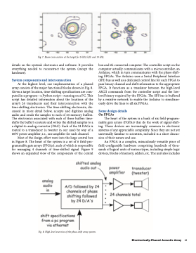
                  Fig. 7. Beam cross-section at the target for 5 kHz (left) and 10 kHz.
details on the system’s electronics and software. It provides everything needed to reconstruct the system (except the hardware).
System components and interconnection
At the highest level, our implementation of a phased array consists of the major functional blocks shown in Fig. 8. Given a target location, time-shifting specifications are com- puted in a program—a Python script—running on a PC. This script has detailed information about the locations of the array’s 24 transducers and their interconnection with the time-shifting electronics. The time-shifting electronics, dis- cussed in more detail below, accepts and digitizes analog audio and sends the samples to each of 24 memory buffers. The electronics associated with each of these buffers time- shifts the buffer’s contents and writes the shifted samples to a a digital-to-analog converter (DAC). Each of the 24 DACs is routed to a transducer (a tweeter in our case) by way of a 60W power amplifier; i.e., one amplifier for each channel.
Most of the design effort went into the large central box in Figure 8. The heart of the system is a set of 6 field-pro- grammable gate arrays (FPGAs), each of which is responsible for managing 4 channels of time-shifted signal. Figure 9 shows an expanded view of the components of the central
box and it’s connected computer. The controller script on the computer actually communicates with a microcontroller, an Arduino, which in turn communicates with the phase-shift- ing FPGAs. The Arduino uses a Serial Peripheral Interface (SPI) bus as well as a dedicated control line for each FPGA to pass binary channel and shift information to the appropriate FPGA. It functions as a translator between the high-level ASCII commands from the controller script and the low- level binary required by the FPGAs. The SPI bus is buffered by a resistive network to enable the Arduino to simultane- ously drive the lines to all six FPGAs.
Some design details
On FPGAs
The heart of the system is a bank of six field-program- mable gate arrays (FGPAs) that do the work of signal-shift- ing. These devices are increasingly common in electronic systems of any appreciable complexity. Since they are not yet universally familiar to scientists, included is a short discus- sion of their nature and use.
An FPGA is a complex, miraculously versatile piece of field-configurable hardware comprising hundreds of thou- sands of logical units of various types, including simple logic devices, blocks of memory, adders, etc. The unit also includes
  Fig. 8. High-level overview of the phase-shift array system.
Electronically-Phased Acoustic Array 25
